Step 1
Locate switchboard location and mark height
Step 2
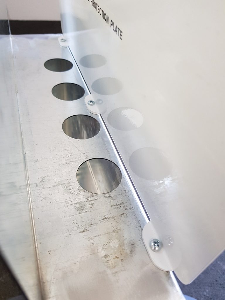
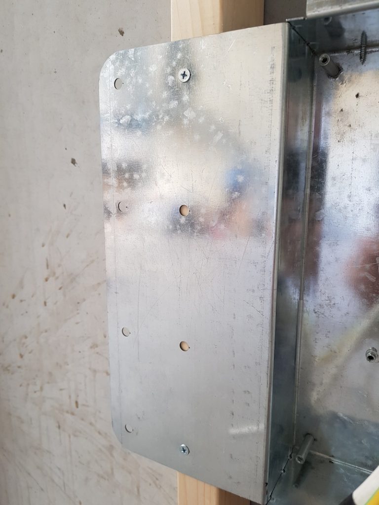
Unpack the sub board and screw fix mechanical protection plate to top or bottom of mounting box using 3 x 6G Self Tapping screws (Supplied) – depending on cables entry side.
Step 3
Place mounting box into position between two studs
Step 4
Using 4 x undercut self tapping screws (supplied) fix mounting box back to studs – ensuring that the mounting box is level and the screws have sat evenly into fixing holes
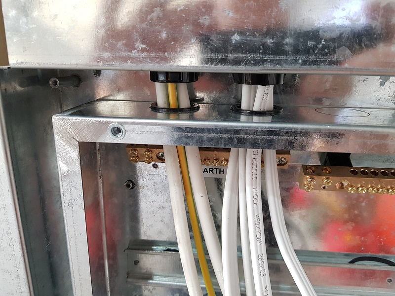
Step 5
Fit snap bushes into desired mounting box entry holes and bring in all required cables
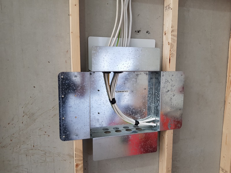
Step 6
Tape and tuck in the cables ready for plastering
Step 7
Mark location of the centre of the mounting box on plans
Step 8
Plastering finished
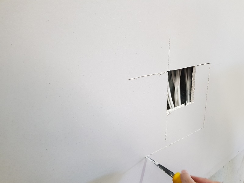
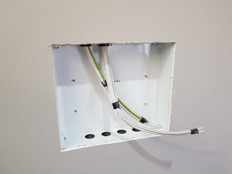
Step 9
Cut out the plaster along the inside edge of the mounting box – watch for cables..
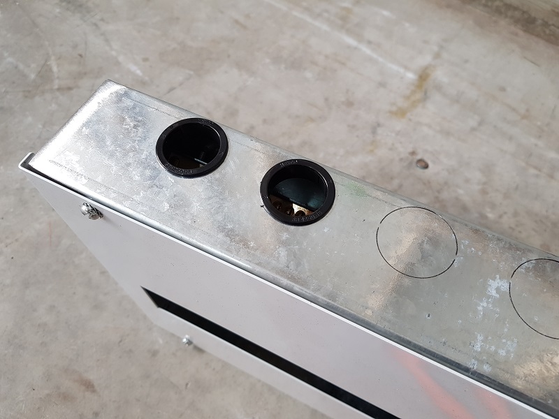
Step 10
On the sub board enclosure knockout the require matching entry holes and fit with snap bushes
Step 11
Bring the cables into the enclosure and push back centre of mounting box – there is 4 x Studs and 4 x holes on the enclosure
Step 12
Fix back enclosure using 4 x nuts and star lock washers
Step 13
Remove the door from door frame kit
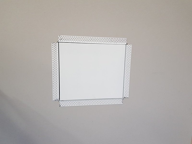
Step 14
Push the frame back over the enclosure and secure in the corners with 4 x star lock washers and 4 x M4*20 screws – ensure to not over tighten. Tighten enough so the plaster bead trim is flush with plaster and the outside edges are not raised.
Step 15
Ensure the frame is level
Step 16
Fit off sub board
Step 17
Re-fit door and close
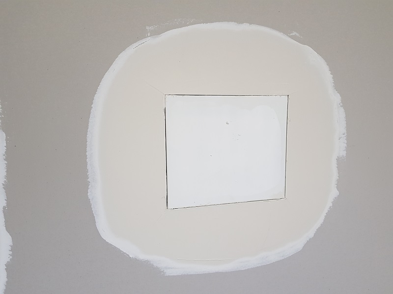
Step 18
Plaster trowel the trim and finish